All-Trol Installation 101 - Part 1.
I bought my first All-Trol Radio Control System (Battery Operation Version) around the first of July in 2008. The All-Trol System is the only complete Radio Control System currently on the market that is made for small scale model trains.
http://www.all-trol.com
I started out by making what I call my "Mule" to test / learn how to wire the system and also to have something to run at my local HO Club. The "Mule", being just the chassis would show all the Radio Control parts and the Battery. This way anyone looking at it would know it was something different.
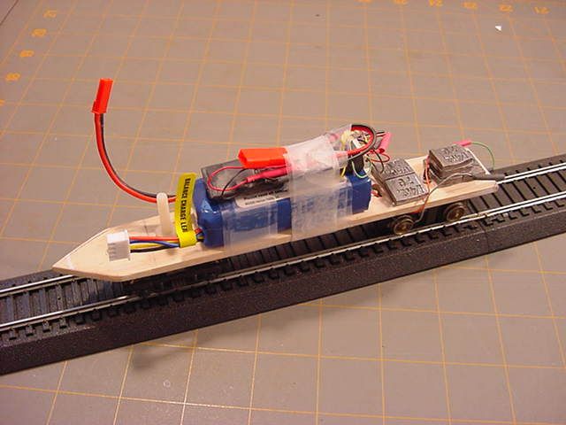
1. Radio Control Test Mule. The Test "Mule" is a piece of Home depot paint stir stick with a front truck and a North West Short Line "PDT" power truck on the rear. The Radio Control Receiver is only wired to the power truck and the 11.1 volt Eflight Battery.
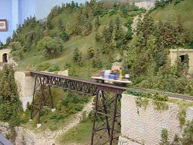
2. Running the "Mule" at my train club, San Antonio Model Railroad Association (SAMRA) - San Antonio, TX.
====
Part 2.
I used a step by step method to learn how to install each component of the All-Trol System, one function at a time.
The first requirement to convert any engine to Radio Control using Battery Power is to make sure it runs well before you start the Radio Control Installation. Radio Control will eliminate track pickup problems but will not help an engine with motor or drive line problems. You must also be sure that track power can not get to the Radio Control Receiver. I remove all wipers from my engines before I instal the Radio Control Receivers. If track power gets to your Radio Control Receiver it can burn it out.
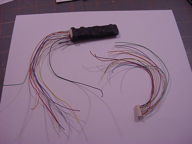
3. All-Trol Receiver - out of the box. The second wiring harness is just to show what it looks like before it is plugged into the Receiver. The wiring harness used is a standard 8 wire item sold by Train Control Systems (TCS). The color coded functions are the same as many of the DCC Decoders being sold today.
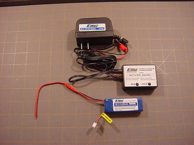
4. I use one of two different type of Batteries. One is a "Team Lois" - 7.4 volt, Lithium Polymer Battery (Li-Po) and the other one is a "Eflight" 11.1 volt Li-Po Battery.
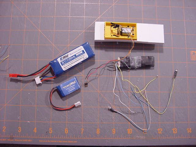
5. Lithium Polymer Batteries "REQUIRE" a special battery charger. Use the charger "made for the battery you are using". The Battery Charger shown is the one made for the Eflight Battery.
=======
Part 3.
I have been building a series of Steeple Cab Models based on a Card Stock Model. Last year Clever Models asked on their Blog if a few folks would like to do a test build of a few card stock - train models. I sent back that I would and was sent three models. One of them was a GE 17 Ton Steeple Cab. It was in O scale. I built it and sent my comments. I had wanted to convert the O scale model to On30 ever since. I few weeks ago I started the conversion and have "kit-bashed" that model into three different Steeple Cabs, all in On30 scale. I have built each one to use the All-Trol Radio Control System. The next pictures will show the RC installation for one of those models.
6. Going back to this picture you can see the donor motor and chassis. It is from the Bachmann HO Ballast Vehicle. I removed the wipers and the DCC ready chip and made a few other modifications so it would fit the On30 Steeple Cab. The only wire I left were the red and black wires coming from the motor. The wires from the RC Receiver to the motor are the Gray and Orange wires. I soldered plugs on each set of wires and plugged them together. The next RC System I install I will change the motor wire to Gray and Orange so the color coding is the same. The Black and Red wires coming out of the RC Receiver connect to the Batteries Black and Red wires. I installed front and rear headlights so I soldered plugs to those wires. The Blue wire is the common wire for both so I made a "Y" connection and joined the three wires. The other wires for the head lights are the Yellow (rear light) and the White (front light). To keep all wiring the same from one install to the next I use the male plug on all wires coming out of the RC Receiver. Their are two extra wires coming out of the receiver (Purple and Green) that are not used when getting your power from a Battery. You can see those two wires wrapped around the receiver and a piece of tape holding them.
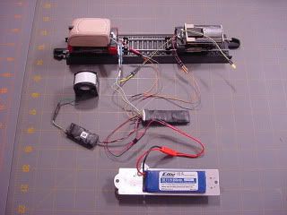
7. This picture shows the completed wiring harness for the Radio Control Installation. I am using the Team Lois Battery for this motor. Note the head light is connected and "on". The rear head light works when the engine is going in reverse.
=========
Part 4.
To show how the All-Trol Sound Module is installed I need to show my scratch built freelance Garratt Locomotive. It will be Radio Control with Batteries and will have a Sound Module.
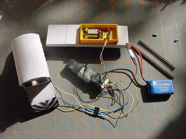
8. this picture shows the wiring harness I made for the RC Installation that goes in the HO scale Garratt. The Sound Module plugs into the RC Receiver. Then you have a pair of wires going from the Sound Module to the Speaker. The Sound Module gets its power and commands from the RC Receiver. The All-Trol Hand Held Controller has buttons to command the sound.
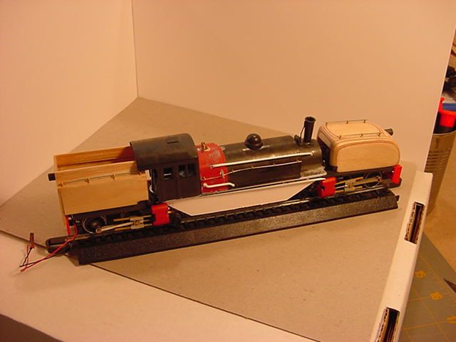
9. This is a picture of the current status of my scratch built freelance HO scale Garratt Locomotive. You can see where I have hidden the Eflight Battery. All wiring is finished and the Speaker is in the Cab. The donor motors are from a pair of modified Bowser Dockside Engines and both run really well. Their will be many more detail parts installed after it is painted.
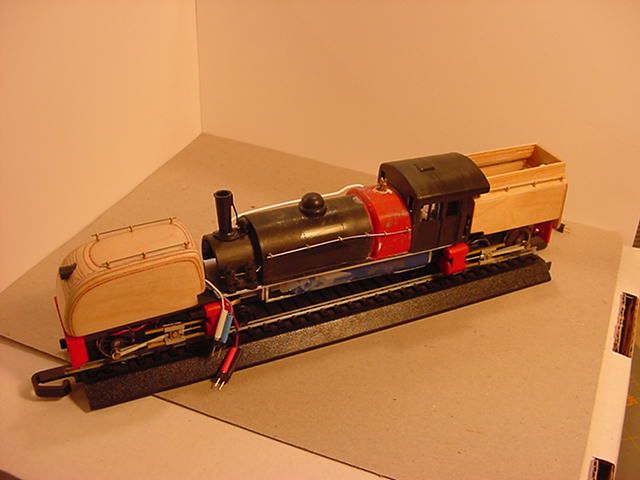
10. This is the other side and the way I have hidden the Battery from slight. The white side piece are a card stock pattern piece. Their will be several detail items attached to that white piece.
==========
I like the All-Trol Radio Control System so well that I now have 7 of their Receivers, two of their Sound Modules and two of their Hand Held Controllers.
No comments:
Post a Comment